The following tables give the mapping of the Raspberry Pi GPIO Pins to the GPIO connector in relation to the pin numbers and the physical location on the connector. This is a representation of the GPIO connector as viewed looking at the board from above, with the USB power at the top and the GPIO to the top-right of the board.
If using the connector pin numbering, then note that Pin 1 on the connector is the 3.3v supply. Pin 2 is the 5V supply, and pin 26 is marked SPI CE1 below.
P1: The Main GPIO connector:
| wiringPi Pin | BCM GPIO | Name | Header | Name | BCM GPIO | wiringPi Pin |
|---|---|---|---|---|---|---|
| – | – | 3.3v | 1 | 2 | 5v | – | – |
| 8 | R1:0/R2:2 | SDA0 | 3 | 4 | 5v | – | – |
| 9 | R1:1/R2:3 | SCL0 | 5 | 6 | 0v | – | – |
| 7 | 4 | GPIO7 | 7 | 8 | TxD | 14 | 15 |
| – | – | 0v | 9 | 10 | RxD | 15 | 16 |
| 0 | 17 | GPIO0 | 11 | 12 | GPIO1 | 18 | 1 |
| 2 | R1:21/R2:27 | GPIO2 | 13 | 14 | 0v | – | – |
| 3 | 22 | GPIO3 | 15 | 16 | GPIO4 | 23 | 4 |
| – | – | 3.3v | 17 | 18 | GPIO5 | 24 | 5 |
| 12 | 10 | MOSI | 19 | 20 | 0v | – | – |
| 13 | 9 | MISO | 21 | 22 | GPIO6 | 25 | 6 |
| 14 | 11 | SCLK | 23 | 24 | CE0 | 8 | 10 |
| – | – | 0v | 25 | 26 | CE1 | 7 | 11 |
| wiringPi Pin | BCM GPIO | Name | Header | Name | BCM GPIO | wiringPi Pin |
- Board Revisions: Please note the differences between board revisions 1 and 2 (R1 and R2 above)
P5: The auxilliary GPIO connector present on Rev. 2 boards only:
| wiringPi Pin | BCM GPIO | Name | Header | Name | BCM GPIO | wiringPi Pin |
|---|---|---|---|---|---|---|
| – | – | 5v | 1 | 2 | 3.3v | – | – |
| 17 | 28 | GPIO8 | 3 | 4 | GPIO9 | 29 | 18 |
| 19 | 30 | GPIO10 | 5 | 6 | GPIO11 | 31 | 20 |
| – | – | 0v | 7 | 8 | 0v | – | – |
| wiringPi Pin | BCM GPIO | Name | Header | Name | BCM GPIO | wiringPi Pin |
Note also that the P5 connector is designed to be used from the underside of the Pi – ie. you solder on the top of the Pi board to install the connector! If you are using it from the top, then you need to mirror the diagram above.
Each side has three columns. The outermost column, headed wiringPi Pin refers to the pin number in the wiring Pi code. The middle one, headed BCM GPIO refers to the pin number of the BCM2835 chip, an this is the pin number used when addressing the GPIO using the/sys/class/gpio interface. The innermost column, Name is the name of the function of the pin.
The central column contains the pin numbers on the header on the board. Pin 1 is the 3.3v power supply on the P1 connector (Rev. 1 and Rev. 2 boards), and Pin 1 is the 5v power supply on the P5 connector on Rev. 2 boards only.
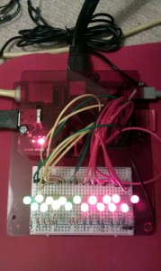
Note: This page was edited (again!) on the 19th of June 2012 to fix the mistakes of the earlier edit. I have double-checked this against the schematic and by building a set of 15 LEDs and connecting it all up.
The photo shows a static shot of a Raspberry Pi driving all 17 GPIO pins with LEDs. The program actually cycles up from Pin 0 to Pin 16 so I can check the exact pin ordering…


No comments:
Post a Comment