Tuesday, November 26, 2013

camera interface in MATLAB


this is the post explains about the how to interface  camera module to the matlab.

Here now i will explain how to connect the your webcam using matlab
by using this application you can do the many type of projects like 
1.security related
2.home appliance controling through the webcam
etc


C it is SEA

INTRODUCTION:
C is the general purpose programming language.developed by Dennis Ritchie.C is the facilitated to the strucutred programming language. 

Wednesday, November 20, 2013

Remote controlled Robo

This is the project where you want control the your devices with Remote it is very helpful.

introduction: This is the project explains about the how to control the robo using the TV remote.

for this project i used the arduino uno board ,tsop(ir remote receive),tv remote which is works like the transmitter.
simply arduino ide i used for the controlling the remote and arduino uno uno board.

connections:

  1. Tsop is connected to the arduio pin 15
  2. L293D which motor driver ic ,for controlling the dc motors to rotate in two direction  connected with micro controller digital pin (as your wish)


for the more information and for project details pls contact
http://potentiallabs.com
http://potentiallabs.com/cart


Wednesday, November 13, 2013

control system using the arduino with ADXL335

Hi these the project explain about the how to control the system using the ADXl335 3d mem sensor or motion sensor.

connections:

1.3 digital pins connected to the arduino to relay board
2.3 analog pins connected to the ADXL335
adxl335 gnd to arduino gnd
adxl335 vcc to arduino 3v3

concept:
using the adxl 335 we can control the system or device using the gestures
simply adxl 335 give the analog values that is connected with the arduino 
so simply arduno receive the values from the analog port by analogread..

by using your hand gestures you can control your home automation and industrial automation

code:

/*

 this is the program to demonstrate the simple

 "Control System Based On Gesture Recognition Using 3D MEMS Accelerometers"

 http://anildurgam.blogspot.com
 sponsred by the potentiallabs
 visit us
 http://potentiallabs.com/
 http://potentiallabs.com/cart
 */


//for controlling the motor directions
//we need 4 digital pins


//motor one control
//int motor1_d1 =7;
int motor1_d2 =8;

//motor two control
int motor2_d1 = 9;
int motor2_d2 = 7;

//Analog read pins
const int xPin = 1;
const int yPin = 2;
const int zPin = 3;

//The minimum and maximum values that came from
//the accelerometer while standing still
//You very well may need to change these
int minVal = 265;
int maxVal = 402;


//to hold the caculated values
double x;
double y;
double z;


//for particular direction
char dir_tion =0;

void setup()
{  

  Serial.begin(9600);
  Serial.print("Robot is ready...give directions");
  Serial.println("\n"); 
  Serial.println("calibrating the time....");
  Serial.println("\n"); 
  //motor pin ...analog pins
 // pinMode(motor1_d1,OUTPUT);
  pinMode(motor1_d2,OUTPUT);

  pinMode(motor2_d1,OUTPUT);
  pinMode(motor2_d2,OUTPUT);
  pinMode(xPin,INPUT);
  pinMode(yPin,INPUT);
  pinMode(zPin,INPUT);


 // digitalWrite(motor1_d1,LOW); 
  digitalWrite(motor1_d2,HIGH); 
  digitalWrite(motor2_d1,HIGH); 
  digitalWrite(motor2_d2,HIGH); 


}


void loop()
{

  //read the analog values from the accelerometer
  int xRead = analogRead(xPin);
  int yRead = analogRead(yPin);
  int zRead = analogRead(zPin);

  //convert read values to degrees -90 to 90 - Needed for atan2
  int xAng = map(xRead, minVal, maxVal, -90, 90);
  int yAng = map(yRead, minVal, maxVal, -90, 90);
  int zAng = map(zRead, minVal, maxVal, -90, 90);

  //Caculate 360deg values like so: atan2(-yAng, -zAng)
  //atan2 outputs the value of -π to π (radians)
  //We are then converting the radians to degrees
  x = RAD_TO_DEG * (atan2(-yAng, -zAng) + PI);
  y = RAD_TO_DEG * (atan2(-xAng, -zAng) + PI);
  z = RAD_TO_DEG * (atan2(-yAng, -xAng) + PI);

  //Output the caculations
  Serial.print("x: ");
  Serial.print(x);
  Serial.print(" | y: ");
  Serial.print(y);
  Serial.print(" | z: ");
  Serial.println(z);

  delay(1000);//just here to slow down the serial output - Easier to read


  //robot move front...hand down..  
  if (x > 210 && x <=230 ) 
  {


    digitalWrite(motor2_d1,HIGH);  

 //   digitalWrite(motor1_d1,LOW); 
    digitalWrite(motor1_d2,LOW); 
    //  digitalWrite(motor2_d1,LOW); 
    digitalWrite(motor2_d2,LOW); 
    delay(1000);

  }

  //robot move right side......hand right ...
  else if(x > 190 && x <=210)
  {

    digitalWrite(motor1_d2,HIGH); 

    //  digitalWrite(motor1_d1,LOW); 
   // digitalWrite(motor1_d1,LOW); 
    digitalWrite(motor2_d1,LOW); 
    digitalWrite(motor2_d2,LOW);

    delay(1000);
  }

  //robot move left side.....hand left........
  else if(x >= 231 && x <= 250)
  {

    digitalWrite(motor2_d2,HIGH); 

   // digitalWrite(motor1_d1,LOW); 
    digitalWrite(motor1_d2,LOW); 
    digitalWrite(motor2_d1,LOW); 
   // digitalWrite(motor2_d2,LOW); 
    delay(1000);
  }


  //stop the robot
  else
  {
    //digitalWrite(motor1_d1,LOW); 
    digitalWrite(motor1_d2,LOW); 
    digitalWrite(motor2_d1,LOW); 
    digitalWrite(motor2_d2,LOW); 
  }

  delay(100);

}


above image shows the values received from the adxl335


Monday, November 11, 2013

what is RISC

Reduced instruction set computing

RISC is abbrevated as reduced instuction set computing.
simply it is like a instructions how to use in the program.if you use less number of instructions not with complecated things then that is called RISC..

Friday, November 8, 2013

LM35(temparature sensor) with arduino

LM35 is the temparature sensor  it give the values those are the analog values .
here i connected the LM 35 with arduino on the analog port.
it is working properly and giving the values..
for pin discription see below the code.

/*

  distance sensor]
 VCC to arduino 5v GND to arduino GND
temp sensor output to Arduino pin 15
 More info at: http://anildurgam.blogspot.in/


sponsred by the potentiallabs
visit us
http://potentiallabs.com/
http://potentiallabs.com/cart


 */


float temp;
int tempPin = 15;

void setup()
{
  Serial.begin(9600);
  pinMode(tempPin ,INPUT);
  Serial.print("serial monitor is ready...waiting for the results");
}

void loop()
{
  temp = analogRead(tempPin);
  temp = temp * 0.48828125;
  Serial.print("TEMPRATURE = ");
  Serial.print(temp);
  Serial.print("*C");
  Serial.println();
  delay(1000);


}

raspberry pi intro


The following tables give the mapping of the Raspberry Pi GPIO Pins to the GPIO connector in relation to the pin numbers and the physical location on the connector. This is a representation of the GPIO connector as viewed looking at the board from above, with the USB power at the top and the GPIO to the top-right of the board.
If using the connector pin numbering, then note that Pin 1 on the connector is the 3.3v supply. Pin 2 is the 5V supply, and pin 26 is marked SPI CE1 below.
P1: The Main GPIO connector:
wiringPi
Pin
BCM
GPIO
NameHeaderNameBCM
GPIO
wiringPi
Pin
3.3v1 | 25v
8R1:0/R2:2SDA03 | 45v
9R1:1/R2:3SCL05 | 60v
74GPIO77 | 8TxD1415
0v9 | 10RxD1516
017GPIO011 | 12GPIO1181
2R1:21/R2:27GPIO213 | 140v
322GPIO315 | 16GPIO4234
3.3v17 | 18GPIO5245
1210MOSI19 | 200v
139MISO21 | 22GPIO6256
1411SCLK23 | 24CE0810
0v25 | 26CE1711
wiringPi
Pin
BCM
GPIO
NameHeaderNameBCM
GPIO
wiringPi
Pin
  • Board Revisions: Please note the differences between board revisions 1 and 2 (R1 and R2 above)
P5: The auxilliary GPIO connector present on Rev. 2 boards only:
wiringPi PinBCM GPIONameHeaderNameBCM GPIOwiringPi Pin
5v1 | 23.3v
1728GPIO83 | 4GPIO92918
1930GPIO105 | 6GPIO113120
0v7 | 80v
wiringPi
Pin
BCM
GPIO
NameHeaderNameBCM
GPIO
wiringPi
Pin
Note also that the P5 connector is designed to be used from the underside of the Pi – ie. you solder on the top of the Pi board to install the connector! If you are using it from the top, then you need to mirror the diagram above.
Each side has three columns. The outermost column, headed wiringPi Pin refers to the pin number in the wiring Pi code. The middle one, headed BCM GPIO refers to the pin number of the BCM2835 chip, an this is the pin number used when addressing the GPIO using the/sys/class/gpio interface. The innermost column, Name is the name of the function of the pin.
The central column contains the pin numbers on the header on the board. Pin 1 is the 3.3v power supply on the P1 connector (Rev. 1 and Rev. 2 boards), and Pin 1 is the 5v power supply on the P5 connector on Rev. 2 boards only.
Note: This page was edited (again!) on the 19th of June 2012 to fix the mistakes of the earlier edit. I have double-checked this against the schematic and by building a set of 15 LEDs and connecting it all up.
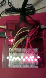
Raspbery Pi driving all 17 GPIO pins

The photo shows a static shot of a Raspberry Pi driving all 17 GPIO pins with LEDs. The program actually cycles up from Pin 0 to Pin 16 so I can check the exact pin ordering…

python class topic video