Wednesday, December 18, 2013

Raspberry Pi with LED ON/OFF

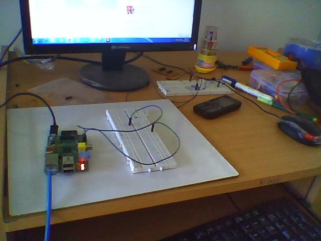
We did a very simple experiment on interfacing a single LED to the GPIO of Raspberry Pi.

The basic circuit diagram is shown below:


Here, we used GPIO8 of the Raspberry Pi and connected it to the LED through a current limiting resistor of 200E.

The python code to blink the LED ON/OFF continuously is shown below:

import RPi.GPIO as GPIO
import time
pinNum = 8
GPIO.setmode(GPIO.BCM) #numbering scheme that corresponds to breakout board and pin layout
GPIO.setup(pinNum,GPIO.OUT) #replace pinNum with whatever pin you used, this sets up that pin as an output
#set LED to flash forever
while True:
  GPIO.output(pinNum,GPIO.HIGH)
  time.sleep(0.5)
  GPIO.output(pinNum,GPIO.LOW) 
  time.sleep(0.5)


To run the above code, save it in any file, say led.py using any text editor. Once saved, run this command to see the LED in action:
sudo python led.py


Change with the different GPIO pins and have a fun...................

Tuesday, December 17, 2013

Raspberry pi with 16x2 lcd display

There are so many example libraries are available...
m also taken from  those examples only..but i modified something and tested lot...

thanks for developers of raspberry pi....

for the connection withe raspberry pi and 16x2 lcd....

pin configuration of the raspberry pi


pin configuration of the16x2 lcd


how to connect the 16x2 display with the raspberry pi


check the code of the python...dump on the raspberry pi


Usually the device requires 8 data lines to provide data to Bits 0-7. However the device can be set to a “4 bit” mode which allows you to send data in two chunks (or nibbles) of 4 bits. This is great as it reduces the number of GPIO connections you require when interfacing with your Pi.
Here is how I wired up my LCD :
LCD PinFunctionPi FunctionPi Pin
01GNDGNDP1-06
02+5V+5VP1-02
03ContrastGNDP1-06
04RSGPIO7P1-26
05RWGNDP1-06
06EGPIO8P1-24
07Data 0
08Data 1
09Data 2
10Data 3
11Data 4GPIO25P1-22
12Data 5GPIO24P1-18
13Data 6GPIO23P1-16
14Data 7GPIO18P1-12
15+5V via 560ohm
16GNDP1-06
NOTE : The RW pin allows the device to be be put into read or write mode. I wanted to send data to the device but did not want it to send data to the Pi so I tied this pin to ground. The Pi can not tolerate 5V inputs on its GPIO header. Tying RW to ground makes sure the device does not attempt to pull the data lines to 5V which would damage the Pi.
In order to control the contrast you can adjust the voltage presented to Pin 3. This must be between 0 and 5V. I tied this pin to ground.
Pin 15 provides 5V to the backlight LED. It wasn’t clear on my device if this could be connected direct to 5V so I played safe and placed a 560ohm resistor in line with this pin.

Python

You can control a HD44780 style display using any programmming environment you like but my weapon of choice is Python. I use the RPi.GPIO library to provide access to the GPIO.
Here is my code :
#!/usr/bin/python
#
# HD44780 LCD Test Script for
# Raspberry Pi
#
# Author : Durgam anil
# Site   : http://potentialabs.com
# Online Store :http://potentiallabs.com/cart
#more info :anildurgam.blogspot.com
# Date   : 17/12/2013
#

# The wiring for the LCD is as follows:
# 1 : GND
# 2 : 5V
# 3 : Contrast (0-5V)*
# 4 : RS (Register Select)
# 5 : R/W (Read Write)       - GROUND THIS PIN
# 6 : Enable or Strobe
# 7 : Data Bit 0             - NOT USED
# 8 : Data Bit 1             - NOT USED
# 9 : Data Bit 2             - NOT USED
# 10: Data Bit 3             - NOT USED
# 11: Data Bit 4
# 12: Data Bit 5
# 13: Data Bit 6
# 14: Data Bit 7
# 15: LCD Backlight +5V**
# 16: LCD Backlight GND

#import
import RPi.GPIO as GPIO
import time

# Define GPIO to LCD mapping
LCD_RS = 7
LCD_E  = 8
LCD_D4 = 25 
LCD_D5 = 24
LCD_D6 = 23
LCD_D7 = 18

# Define some device constants
LCD_WIDTH = 16    # Maximum characters per line
LCD_CHR = True
LCD_CMD = False

LCD_LINE_1 = 0x80 # LCD RAM address for the 1st line
LCD_LINE_2 = 0xC0 # LCD RAM address for the 2nd line 

# Timing constants
E_PULSE = 0.00005
E_DELAY = 0.00005

def main():
  # Main program block

  GPIO.setmode(GPIO.BCM)       # Use BCM GPIO numbers
  GPIO.setup(LCD_E, GPIO.OUT)  # E
  GPIO.setup(LCD_RS, GPIO.OUT) # RS
  GPIO.setup(LCD_D4, GPIO.OUT) # DB4
  GPIO.setup(LCD_D5, GPIO.OUT) # DB5
  GPIO.setup(LCD_D6, GPIO.OUT) # DB6
  GPIO.setup(LCD_D7, GPIO.OUT) # DB7

  # Initialise display
  lcd_init()

  # Send some test
  lcd_byte(LCD_LINE_1, LCD_CMD)
  lcd_string("Rasbperry Pi")
  lcd_byte(LCD_LINE_2, LCD_CMD)
  lcd_string("Model B")

  time.sleep(3) # 3 second delay

  # Send some text
  lcd_byte(LCD_LINE_1, LCD_CMD)
  lcd_string("Potentiallabs")
  lcd_byte(LCD_LINE_2, LCD_CMD)
  lcd_string(".HYDERBAD,INDIA")

  time.sleep(20)

def lcd_init():
  # Initialise display
  lcd_byte(0x33,LCD_CMD)
  lcd_byte(0x32,LCD_CMD)
  lcd_byte(0x28,LCD_CMD)
  lcd_byte(0x0C,LCD_CMD)  
  lcd_byte(0x06,LCD_CMD)
  lcd_byte(0x01,LCD_CMD)  

def lcd_string(message):
  # Send string to display

  message = message.ljust(LCD_WIDTH," ")  

  for i in range(LCD_WIDTH):
    lcd_byte(ord(message[i]),LCD_CHR)

def lcd_byte(bits, mode):
  # Send byte to data pins
  # bits = data
  # mode = True  for character
  #        False for command

  GPIO.output(LCD_RS, mode) # RS

  # High bits
  GPIO.output(LCD_D4, False)
  GPIO.output(LCD_D5, False)
  GPIO.output(LCD_D6, False)
  GPIO.output(LCD_D7, False)
  if bits&0x10==0x10:
    GPIO.output(LCD_D4, True)
  if bits&0x20==0x20:
    GPIO.output(LCD_D5, True)
  if bits&0x40==0x40:
    GPIO.output(LCD_D6, True)
  if bits&0x80==0x80:
    GPIO.output(LCD_D7, True)

  # Toggle 'Enable' pin
  time.sleep(E_DELAY)    
  GPIO.output(LCD_E, True)  
  time.sleep(E_PULSE)
  GPIO.output(LCD_E, False)  
  time.sleep(E_DELAY)      

  # Low bits
  GPIO.output(LCD_D4, False)
  GPIO.output(LCD_D5, False)
  GPIO.output(LCD_D6, False)
  GPIO.output(LCD_D7, False)
  if bits&0x01==0x01:
    GPIO.output(LCD_D4, True)
  if bits&0x02==0x02:
    GPIO.output(LCD_D5, True)
  if bits&0x04==0x04:
    GPIO.output(LCD_D6, True)
  if bits&0x08==0x08:
    GPIO.output(LCD_D7, True)

  # Toggle 'Enable' pin
  time.sleep(E_DELAY)    
  GPIO.output(LCD_E, True)  
  time.sleep(E_PULSE)
  GPIO.output(LCD_E, False)  
  time.sleep(E_DELAY)   

if __name__ == '__main__':
  main()
the output look like this


Thursday, December 12, 2013

servo motor with arduino

this is the post explains about the how to connect the arduino with the servo motor.

mainly servo motor having 3 pins
1.5v supply
2.gnd
3.output pin

pls see the below image for the better connections


pls check the code


#include <Servo.h>

Servo myservo;  // create servo object to control a servo

int potpin = 0;  // analog pin used to connect the potentiometer
int val;    // variable to read the value from the analog pin

void setup()
{
  myservo.attach(9);  // attaches the servo on pin 9 to the servo object
}

void loop()
{
  val = analogRead(potpin);            // reads the value of the potentiometer (value between 0 and 1023)
  val = map(val, 0, 1023, 0, 179);     // scale it to use it with the servo (value between 0 and 180)
  myservo.write(val);                  // sets the servo position according to the scaled value
  delay(15);                           // waits for the servo to get there
}


pls watch the video for more clear explanation


optimisation of the vlsi architecture in the wireless sensor network

ABSTRACT
Optimisation of vlsi architecture in wireless sensor network (WSN) scheme for fusion centre to detect the faults of sensor nodes via efficient collaborative sensor fault detection (ECSFD), these scheme identifies the sensor node fault percentage and its efficiency of the particular sensor node. In real world most of the applications of WSN are based on ASIC and the standalone devices. So this optimized efficient
collaborative wireless sensor fault detection scheme is less expensive area of the chip is very less and fast in performance.
Index Terms — Wireless sensor network, Collaborative sensor fault detection, Efficient collaborative sensor fault detection, Fusion centre, Fault detection.

for full base paper , visit the link:
http://warse.org/pdfs/2013/icacsesp51.pdf

Wednesday, December 11, 2013

Installing an Arduino Bootloader

Installing an Arduino Bootloader

Overview

Do you have a bricked Arduino that won’t accept code anymore? Or, maybe you wrote your own firmware and would like to upload it to your Arduino? Or, maybe you just want to learn more about the inner-workings of Arduino, AVR, and microcontrollers in general. Well, you’re in luck! This tutorial will teach you what a bootloader is, why you would need to install/reinstall it, and go over the process of doing so.

What is a Bootloader?

Atmel AVRs are great little ICs, but they can be a bit tricky to program. You need a special programmer and some fancy .hex files, and its not very beginner friendly. The Arduino has largely done away with these issues. They’ve put a .hex file on their AVR chips that allows you to program the board over the serial port, meaning all you need to program your Arduino is a USB cable.
The bootloader is basically a .hex file that runs when you turn on the board. It is very similar to the BIOS that runs on your PC. It does two things. First, it looks around to see if the computer is trying to program it. If it is, it grabs the program from the computer and uploads it into the ICs memory (in a specific location so as not to overwrite the bootloader). That is why when you try to upload code, the Arduino IDE resets the chip. This basically turns the IC off and back on again so the bootloader can start running again. If the computer isn’t trying to upload code, it tells the chip to run the code that’s already stored in memory. Once it locates and runs your program, the Arduino continuously loops through the program and does so as long as the board has power.

Why Install a Bootloader

If you are building your own Arduino, or need to replace the IC, you will need to install the bootloader. You may also have a bad bootloader (although this is very rare) and need to reinstall the bootloader. There are also cases where you’ve put your board in a weird setting and reinstalling the bootloader and getting it back to factory settings is the easiest way to fix it. We’ve seen boards where people have turned off the serial port meaning that there is no way to upload code to the board, while there may be other ways to fix this, reinstalling the bootloader is probably the quickest and easiest. Like I said, having a bad bootloader is actually very very rare. If you have a new board that isn’t accepting code 99.9% of the time its not the bootloader, but for the 1% of the time it is, this guide will help you fix that problem.

Selecting a Programmer

We are going to talk about 2 different types of programmers you can use to install or reinstall bootloaders.

Option 1: Dedicated Programmers

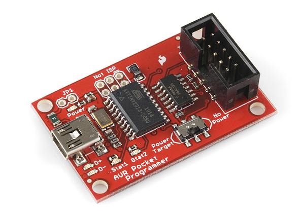
For a quick easy programmer we recommend looking into the AVR Pocket Programmer (Windows only).
pocket programmer
Or, you can use the official Atmel AVR MKII programmer.
AVR MKII
The AVR Pocket Programmer or most cheaper options will work just fine for most applications, but they may have problems with some boards, specifically ones with lots of memory like the ATMega2560 based boards.

Option 2: Using the Arduino as a Programmer

The other option is grabbing an Arduino Uno (or Duemilanove). If you go into the Arduino IDE you will see an example sketch called ‘Arduino as ISP.’ If you upload this code to your Arduino, it will basically act as an AVR programmer. This isn’t really recommended for production of boards, or boards with lots of memory, but, in a pinch, it works pretty well. Also as of this writing the code only works on ATmega328 boards. Maybe one day it will work on the Leonardo or Due, but not yet.
Note: You can only use Arduinos that have a DIP IC and a socket like this Uno, not Arduinos that have SMD ATmegas on them, such as the RedBoard.

Connecting the Programmer

In-Circuit Serial Programming (ICSP)

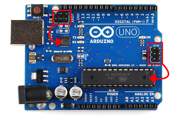
It’s very uncommon to program ICs before they are soldered onto a PCB. Instead, most microcontrollers have what’s called an in-system programming (ISP) header. Particularly, some IC manufacturers, such as Atmel and Microchip, have a specialized ISP method for programming their ICs. This is referred to as in-circuit serial programming (ICSP) Most Arduino and Arduino compatible boards will have a 2x3 pin ICSP header on them. Some may even have more than one depending on how many ICs live on the PCB. It breaks out three of the SPI pins (MISO, MOSI, SCK), and power, ground, and reset. These are the pins you’ll need to connect your programmer to in order to reflash the firmware on your board.
UNO ISP
Here we have the Arduino Uno R3. It has two ICSP headers: one for the ATmega16U2 and one for the ATmega328. To reflash the bootloader on this board, you would use just the ICSP header for the ATmega328.
On some smaller boards you may not see this connector, but the pins should be broken out elsewhere. Whether you’re using an SMD IC or a DIP IC, the ISP pins should be accessible in one form or another. Some boards might only have test points for the ISP header. If this is the case, you may want to consider getting an ISP Pogo Adapter. This kit allows you to temporarily make a good connection with test test points in order to reprogram your IC.
alt text
ISP Pogo Adapter Kit Fully Assembled. You can connect any of the programmers we mentioned in the previous section to this board.
If you are having trouble finding the ICSP pins on your particular Arduino board, you can consult this website for detailed pinouts of most Arduino related ICs and then some.
Once you have located the six ICSP pins on your board, it’s time to hook up your programmer to the board. You can use aprogramming cable to connect the two, or, if you don’t have a cable, you can just use some male-to-female jumper wires.
If you are using a programmer such as the MKII or the Pocket Programmer, your setup should look something like this:
alt text
Click for larger image.
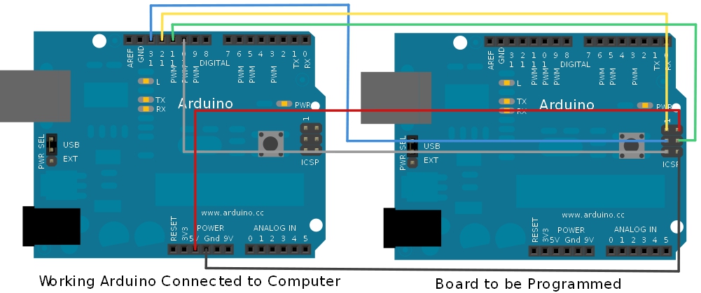
Or, if you’re using the Arduino as your programmer, it should look like this:
alt text
Click for larger image.
Here’s a table to help clarify which connections go where.
Arduino as ISPAVR ProgrammerISP HeaderATmega328ATmega32U4
Vcc/5V5VPin 2VccVcc
GNDGNDPin 6GNDGND
MOSI/D11MOSIPin 4D11D16
MISO/D12MISOPin 1D12D14
SCK/D13SCKPin 3D13D15
D10ResetPin 5ResetReset


Uploading Code - Easy Way

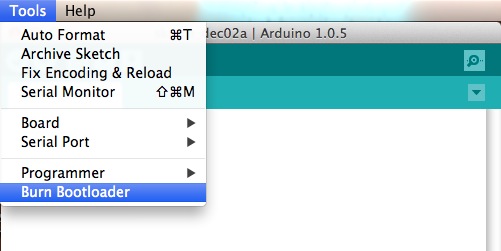
The easy way to upload the bootloader involves using the Arduino IDE. Open your IDE select the board you want to program. Then select the programmer (if you are using the Arduino as ISP you will also need to select the COM port that the Arduino as ISP is connected to). Then select BurnBootloader. This will take the board you selected and look up the associated bootloader in the board.txt file. Then, it will find the bootloader in the bootloader folder and install it. This only works if the board is installed correctly in the IDE and you have the correct bootloader.
If for some reason you want to use a bootloader that isn’t installed in the Arduino IDE, visit the nest section. However, it’s probably easier to just install the bootloader from the Arduino IDE. For those who are curious about settings such as fuse bits, have no fear. Arduino takes care of all the messy details for you when you burn bootloaders through it.
alt text


Uploading Code - Hard Way

The hard way is for those people who want to use the command line. This method may be more preferable if you are modifying and recompiling and don’t want to have to keep updating the IDE, but otherwise its pretty unnecessary. Again you will need to get the programmer, and hook everything up. In this example we are using avrdude on Windows.
There are two steps to this process. The first step involves setting the fusebits. Fusebits are the part of the AVR chip that determine things like whether you are using an external crystal or whether you want brown out detection. The commands listed below are for the Arduino Uno using an ATMega328, they will probably work on some other similar boards such as the Duemilanove, but make sure you know what you are doing before playing with fusebits (NOTE: these fusebits will not work on a 3.3V/8MHz board). All the required fuse bits are listed in the boards.txt file for different boards, but again, if you have a boards.txt file installed then just use the Easy Way.
Arduino as ISP:avrdude -P comport -b 19200 -c avrisp -p m328p -v -e -U efuse:w:0x05:m -U hfuse:w:0xD6:m -U lfuse:w:0xFF:m
AVR Pocket Programmer:avrdude -b 19200 -c usbtiny -p m328p -v -e -U efuse:w:0x05:m -U hfuse:w:0xD6:m -U lfuse:w:0xFF:m
The second step is actually uploading the program.
Arduino as ISP: avrdude -P comport -b 19200 -c avrisp -p m328p -v -e -U flash:w:hexfilename.hex -U lock:w:0x0F:m AVR Pocket Programmer: avrdude -b19200 -c usbtiny -p m328p -v -e -U flash:w:hexfilename.hex -U lock:w:0x0F:m
One last bit of info. As we stated earlier, a bootloader is essintially a .hex file. Thus, you can use this method to upload and code you wish to your ICs.


python class topic video