Django html tags display:
========================
By writing html tags you can achieve the output
go into views.py file
def menu(request):
return HttpResponse("<h1>This is working menu</h1>");
Django html tags display:
========================
By writing html tags you can achieve the output
go into views.py file
def menu(request):
return HttpResponse("<h1>This is working menu</h1>");
django installation process:
=============================
pip install virtualenvwrapper-win
mkvirtualenv test
pip install django
django-admin --version
mkdir yourfolder
cd yourfolder
django-admin startproject yourprojectname
python manage.py runserver
to create virtual environment in vscode:
=======================================
workon "base"
python manage.py startapp yourapp
creating your app:
=======================
create urls.py in your app
urlpatterns=[
path('',views.home,name='home')
]
go into views.py
add :from django.http import HttpResponse
create a function home
def home(request):
return HttpResponse("we are into our own page");
go into urls project:
add below line
path('',include('yourapp.urls'))
AT commands
testing on ESP32-WROOM-32
ESP32-WROOM-32 PINOUT DIAGRAM
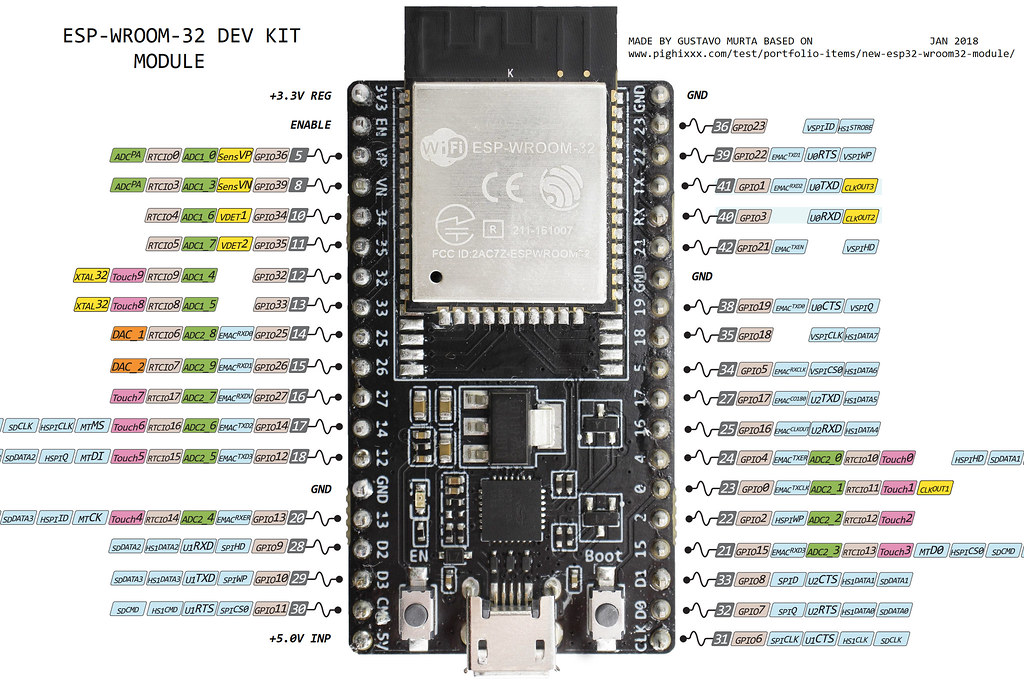
ESP32-WROOM-32 -
ESP32-WROOM-32 module soldered to the development board. Optionally
ESP32-WROOM-32D, ESP32-WROOM-32U or ESP32-SOLO-1 module may be soldered instead
of the ESP32-WROOM-32.
USB-UART
Bridge - A single chip USB-UART bridge provides up to
3 Mbps transfers rates.
BOOT button
- Download button: holding down the Boot button and pressing the EN button
initiates the firmware download mode. Then user can download firmware through
the serial port.
EN button
- Reset button: pressing this button resets the system.
Micro
USB Port - USB interface. It functions as the power
supply for the board and the communication interface between PC and the ESP
module.
TX0,
TX2 - transmit pin. GPIO pin
RX0,
RX2 - receive pin. GPIO pin
3V3
(or 3V or 3.3V) - power supply pin (3-3.6V).
GND -
ground pin.
EN -
Chip enable. Keep it on high (3.3V) for normal operation.
Vin -
External power supply 5VDC.
1. Uploading AT firmware/Firmware upgrade
CONNECTIONS :
·
Attach USB cable one side to ESP32-WROOM-32
·
Connect the another end PC/LAPTOP
Shown below

2. Using USB
to TTL converter for AT communication

ESP32-WROOM-32 firmware versions
ESP32-WROOM-32
AT Bin V1.1.1 2018.07.11
ESP32-WROOM-32
AT Bin V1.1 2018.06.13
ESP32-WROOM-32
AT Bin V1.0 2017.11.17
ESP32-WROOM-32
AT Bin V0.10 2017.06.14
1. Do wiring for uploading
AT firmware/firmware update.
2. Download Flash
Download Tools (ESP8266 & ESP32) from espressif.com.
The
ESP32 Flash Download Tool, just like the ESP8266 download tool, is the official
Espressif Download tool that runs on Windows platform. The tool can be used to
modify and generate init BINs, generate consolidated BIN files or program
multiple chips for production runs.
The
tool uses COM port to send BIN files from PC to the ESP32, which then flashes
the data to the primary flash chip.
The
ESP32 Flash Download Tool, just like the ESP8266 download tool, is the official
Espressif Download tool that runs on Windows platform. The tool can be used to
modify and generate init BINs, generate consolidated BIN files or program
multiple chips for production runs.
The tool uses COM port to send BIN files from PC to the ESP32, which then
flashes the data to the primary flash chip.
3. Download and unzip the
latest AT firmware for your module (Check which module you have, for example we
have ESP32-WROOM-32). We used this firmware here: ESP32-WROOM-32 AT Bin V1.1.1 2018.07.11
4. Go to the
folder ESP32-WROOM-32_AT_V1.1.1 and find file named download.config.

AT commands firmware
for memory locations
1. bootloader.bin:0x1000
2. at_customize.bin:0x20000
3. server_cert.bin:0x24000
4. server_key.bin:0x26000
5. server_ca.bin:0x28000
6. client_cert.bin:0x2a000
7. client_key.bin:0x2c000
8. client_ca.bin:0x2e000
9. phy_init_data.bin:0xf000
10. esp-at.bin:0x100000
11. partitions_at.bin:0x8000
Download tool


After flashing the
firmware

To communicate (use AT commands) with ESP32
development board you need USB to TTL converter.
For using this USB to UART Converter you need
a software tool. You can use different software tools: Terminal, USR-TCP232-Test V1.4, AiThinker_Serial_Tool_V1.2.3, coolterm, sscom3.2 , KiTTY, putty,tera term, Access port and so
on. We recommend you to use AiThinker_Serial_Tool_V1.2.3 or sscom3.2,
as you can save your AT commands and it's very easy to use.
Results

Using simple serial/UART communication using we can connect with MM32 mcu with EC20 gsm modules.
please find the code below
/* USER CODE BEGIN Header */
/**
******************************************************************************
* @file : main.c
* @brief : Main program body
******************************************************************************
* @attention
*
* <h2><center>© Copyright (c) 2020 STMicroelectronics.
* All rights reserved.</center></h2>
*
* This software component is licensed by ST under BSD 3-Clause license,
* the "License"; You may not use this file except in compliance with the
* License. You may obtain a copy of the License at:
* opensource.org/licenses/BSD-3-Clause
*
******************************************************************************
*/
/* USER CODE END Header */
/* Includes ------------------------------------------------------------------*/
#include "main.h"
/* Private includes ----------------------------------------------------------*/
/* USER CODE BEGIN Includes */
/* USER CODE END Includes */
/* Private typedef -----------------------------------------------------------*/
/* USER CODE BEGIN PTD */
RTC_TimeTypeDef sTime = {0};
RTC_DateTypeDef sDate = {0};
RTC_AlarmTypeDef sAlarm = {0};
/* USER CODE END PTD */
/* Private define ------------------------------------------------------------*/
/* USER CODE BEGIN PD */
/* USER CODE END PD */
/* Private macro -------------------------------------------------------------*/
/* USER CODE BEGIN PM */
/* USER CODE END PM */
/* Private variables ---------------------------------------------------------*/
RTC_HandleTypeDef hrtc;
/* USER CODE BEGIN PV */
/* USER CODE END PV */
/* Private function prototypes -----------------------------------------------*/
void SystemClock_Config(void);
static void MX_RTC_Init(void);
/* USER CODE BEGIN PFP */
/* USER CODE END PFP */
/* Private user code ---------------------------------------------------------*/
/* USER CODE BEGIN 0 */
/* USER CODE END 0 */
/**
* @brief The application entry point.
* @retval int
*/
int main(void)
{
/* USER CODE BEGIN 1 */
/* USER CODE END 1 */
/* MCU Configuration--------------------------------------------------------*/
/* Reset of all peripherals, Initializes the Flash interface and the Systick. */
HAL_Init();
/* USER CODE BEGIN Init */
/* USER CODE END Init */
/* Configure the system clock */
SystemClock_Config();
/* USER CODE BEGIN SysInit */
/* USER CODE END SysInit */
/* Initialize all configured peripherals */
MX_RTC_Init();
/* USER CODE BEGIN 2 */
sTime.Hours = 11;
sTime.Minutes = 17;
sTime.Seconds = 10;
HAL_RTC_SetTime(&hrtc, &sTime, RTC_FORMAT_BIN);
sDate.WeekDay = RTC_WEEKDAY_FRIDAY;
sDate.Month = RTC_MONTH_SEPTEMBER;
sDate.Date = 25;
sDate.Year = 2020;
HAL_RTC_SetDate(&hrtc,&sDate, RTC_FORMAT_BIN);
HAL_Delay(200);
/* USER CODE END 2 */
/* Infinite loop */
/* USER CODE BEGIN WHILE */
while (1)
{
/* USER CODE END WHILE */
HAL_RTC_GetTime(&hrtc, &sTime, RTC_FORMAT_BIN);
HAL_RTC_GetDate(&hrtc,&sDate, RTC_FORMAT_BIN);
HAL_Delay(200);
/* USER CODE BEGIN 3 */
}
/* USER CODE END 3 */
}
/**
* @brief System Clock Configuration
* @retval None
*/
void SystemClock_Config(void)
{
RCC_OscInitTypeDef RCC_OscInitStruct = {0};
RCC_ClkInitTypeDef RCC_ClkInitStruct = {0};
RCC_PeriphCLKInitTypeDef PeriphClkInitStruct = {0};
/** Configure the main internal regulator output voltage
*/
__HAL_RCC_PWR_CLK_ENABLE();
__HAL_PWR_VOLTAGESCALING_CONFIG(PWR_REGULATOR_VOLTAGE_SCALE1);
/** Initializes the CPU, AHB and APB busses clocks
*/
RCC_OscInitStruct.OscillatorType = RCC_OSCILLATORTYPE_HSI|RCC_OSCILLATORTYPE_LSI;
RCC_OscInitStruct.HSIState = RCC_HSI_ON;
RCC_OscInitStruct.HSICalibrationValue = RCC_HSICALIBRATION_DEFAULT;
RCC_OscInitStruct.LSIState = RCC_LSI_ON;
RCC_OscInitStruct.PLL.PLLState = RCC_PLL_NONE;
if (HAL_RCC_OscConfig(&RCC_OscInitStruct) != HAL_OK)
{
Error_Handler();
}
/** Initializes the CPU, AHB and APB busses clocks
*/
RCC_ClkInitStruct.ClockType = RCC_CLOCKTYPE_HCLK|RCC_CLOCKTYPE_SYSCLK
|RCC_CLOCKTYPE_PCLK1|RCC_CLOCKTYPE_PCLK2;
RCC_ClkInitStruct.SYSCLKSource = RCC_SYSCLKSOURCE_HSI;
RCC_ClkInitStruct.AHBCLKDivider = RCC_SYSCLK_DIV1;
RCC_ClkInitStruct.APB1CLKDivider = RCC_HCLK_DIV1;
RCC_ClkInitStruct.APB2CLKDivider = RCC_HCLK_DIV1;
if (HAL_RCC_ClockConfig(&RCC_ClkInitStruct, FLASH_LATENCY_0) != HAL_OK)
{
Error_Handler();
}
PeriphClkInitStruct.PeriphClockSelection = RCC_PERIPHCLK_RTC;
PeriphClkInitStruct.RTCClockSelection = RCC_RTCCLKSOURCE_LSI;
if (HAL_RCCEx_PeriphCLKConfig(&PeriphClkInitStruct) != HAL_OK)
{
Error_Handler();
}
}
/**
* @brief RTC Initialization Function
* @param None
* @retval None
*/
static void MX_RTC_Init(void)
{
/* USER CODE BEGIN RTC_Init 0 */
/* USER CODE END RTC_Init 0 */
RTC_TimeTypeDef sTime = {0};
RTC_DateTypeDef sDate = {0};
RTC_AlarmTypeDef sAlarm = {0};
/* USER CODE BEGIN RTC_Init 1 */
/* USER CODE END RTC_Init 1 */
/** Initialize RTC Only
*/
hrtc.Instance = RTC;
hrtc.Init.HourFormat = RTC_HOURFORMAT_24;
hrtc.Init.AsynchPrediv = 127;
hrtc.Init.SynchPrediv = 255;
hrtc.Init.OutPut = RTC_OUTPUT_DISABLE;
hrtc.Init.OutPutPolarity = RTC_OUTPUT_POLARITY_HIGH;
hrtc.Init.OutPutType = RTC_OUTPUT_TYPE_OPENDRAIN;
if (HAL_RTC_Init(&hrtc) != HAL_OK)
{
Error_Handler();
}
/* USER CODE BEGIN Check_RTC_BKUP */
/* USER CODE END Check_RTC_BKUP */
/** Initialize RTC and set the Time and Date
*/
sTime.Hours = 10;
sTime.Minutes = 35;
sTime.Seconds = 10;
sTime.DayLightSaving = RTC_DAYLIGHTSAVING_NONE;
sTime.StoreOperation = RTC_STOREOPERATION_RESET;
if (HAL_RTC_SetTime(&hrtc, &sTime, RTC_FORMAT_BIN) != HAL_OK)
{
Error_Handler();
}
sDate.WeekDay = RTC_WEEKDAY_FRIDAY;
sDate.Month = RTC_MONTH_SEPTEMBER;
sDate.Date = 25;
sDate.Year = 2020;
if (HAL_RTC_SetDate(&hrtc, &sDate, RTC_FORMAT_BIN) != HAL_OK)
{
Error_Handler();
}
/** Enable the Alarm A
*/
sAlarm.AlarmTime.Hours = 0;
sAlarm.AlarmTime.Minutes = 0;
sAlarm.AlarmTime.Seconds = 0;
sAlarm.AlarmTime.SubSeconds = 0;
sAlarm.AlarmTime.DayLightSaving = RTC_DAYLIGHTSAVING_NONE;
sAlarm.AlarmTime.StoreOperation = RTC_STOREOPERATION_RESET;
sAlarm.AlarmMask = RTC_ALARMMASK_NONE;
sAlarm.AlarmSubSecondMask = RTC_ALARMSUBSECONDMASK_ALL;
sAlarm.AlarmDateWeekDaySel = RTC_ALARMDATEWEEKDAYSEL_DATE;
sAlarm.AlarmDateWeekDay = 1;
sAlarm.Alarm = RTC_ALARM_A;
if (HAL_RTC_SetAlarm_IT(&hrtc, &sAlarm, RTC_FORMAT_BIN) != HAL_OK)
{
Error_Handler();
}
/* USER CODE BEGIN RTC_Init 2 */
/* USER CODE END RTC_Init 2 */
}
/* USER CODE BEGIN 4 */
/* USER CODE END 4 */
/**
* @brief This function is executed in case of error occurrence.
* @retval None
*/
void Error_Handler(void)
{
/* USER CODE BEGIN Error_Handler_Debug */
/* User can add his own implementation to report the HAL error return state */
/* USER CODE END Error_Handler_Debug */
}
#ifdef USE_FULL_ASSERT
/**
* @brief Reports the name of the source file and the source line number
* where the assert_param error has occurred.
* @param file: pointer to the source file name
* @param line: assert_param error line source number
* @retval None
*/
void assert_failed(uint8_t *file, uint32_t line)
{
/* USER CODE BEGIN 6 */
/* User can add his own implementation to report the file name and line number,
tex: printf("Wrong parameters value: file %s on line %d\r\n", file, line) */
/* USER CODE END 6 */
}
#endif /* USE_FULL_ASSERT */
/************************ (C) COPYRIGHT STMicroelectronics *****END OF FILE****/
https://drive.google.com/file/d/1s1pKxCdkc1oZJDfm-WhoNq1UeWmM2W1r/view?usp=sharing
to download file click above link
https://drive.google.com/file/d/14yXySxDJGcEgbD1S2hihYivG_d6Abnru/view?usp=sharing
please find the code in the above link
https://drive.google.com/file/d/1Zyx4rBlSR2JztSptzlotNiWERkFhuqs7/view?usp=sharing
please download the above link
#include <stdio.h>
/* print Fahrenheit-Celsius table
for fahr = 0, 20, ..., 300 */
int main(void)
{
float fahr, celsius;
int lower, upper, step;
lower = 0;
upper = 300;
step = 20;
/* lower limit of temperature table *1
1* upper limit *1
1* step size */
fahr = lower;
while (fahr <= upper)
{
celsius = 5.0/9.0 * (fahr-32.0) ;
printf("%3.0f \t %6.1f\n", fahr, celsius);
/*
%d print as decimal integer
%6d print as decimal integer, at least 6 characters wide print as floating point
%6f print as floating point, at least 6 characters wide
%.2f print as floating point, 2 characters after decimal point
%6.2f print as floating point, at least 6 wide and 2 after decimal point
*/
fahr = fahr + step;
}
}
1.Micro Controller
Voltage Range?
Ans: In MM32 microcontroller range lot of Microcontrollers available.So It is depends upon the particular microcontroller
2. Can i give 9v/12v
power supply directly to microcontroller?
Ans: Most of the MM32 microcontrollers supports 5VDC. So better check datasheet before connecting
3. is there any power
protection kind of thing in this MC?
Ans: no special protection is available
4. Which IDE supports
for MM32 microcontrollers ?
Ans: 1.Keil Uvision,2.IAR 3.Eclipse (GCC)
5. How to install
Keil IDE ?
Ans: "1.First we Need to download the Keil IDE
2.After installation we need to Click on Packages
3.Then search and install MM32 microcontroller package"
6. How to install in
Eclipse ?
Ans: please refer the document
7. is support for
arduino IDE ?
Ans: No
8. How to install in
using GCC?
Ans: please refer the document
9. Is there any
debugg support for MM32?
Ans: yes
10. Is datasheets available for MM32
microcontrollers?
Ans: Yes
11. Is user manual
available for MM32 microcontrollers?
Ans: Present not available.
12. Reference
Schematics available or not?
Ans: Available
13. PCB files
available or not?
Ans: Available
14. where i will get
the documents ?
Ans: Available in our website & http://183.82.99.162:8000/Mind%20Motion%20Controller/Data/
15. Can i directly
download?
Ans: yes.They are free to download
16. Any tutorial
available for this?
Ans: No
17. How to
Dump/Burn/Upload the code into microcontroller?
Ans: Using MM32 link
18. What are pins
available for MM32 Link to upload the code ?
Ans: SWDIO,SWCLK,NRST,VCC,GND
19. Can i upload the
code using ST-link ?
Ans: yes(Using Keil IDE Only)
20. How many pin are
there in MM32 link ?
Ans: SWDIO,SWCLK,NRST,VCC,GND,TX,RX pins available
21. what is
communication protocol used to dump the code ?
Ans: JTAG
22. can i directly
connect with microcontroller with MM32link to dump the code?
Ans: yes, but check the connections before giving power supply
23. Is it Support
UART protocol?
Ans: yes
24. How many max
UART's available in MM32 microcontrollers ?
Ans: 8 UART'S available
25. Is this
microcontroller support SPI protocol ?
Ans: yes
26. How many max
SPI's available in MM32 Microcontrollers?
Ans: 3 SPI's
27. Is it support I2C
protocol ?
Ans: yes
28. is it every
microcontroller support for CAN protocol in MM32 microcontrollers?
Ans: No, Only Few microcontroller support CAN protocol
29. What kind of
securities MM32 provide ?
Ans: AES
30. Can we make new
project coding from the scratch in Keil IDE?
Ans: Yes, But already Examples are available in Lib directory. Modify them according to requirements
31. is there
libraries available for MM32 microcontroller ?
Ans: Yes
32. is there any
examples available for MM32 microcontrollers?
Ans: yes
33. where is program
will be stored ?
Ans: internal flash memory
34. How many Gpio
available in MM32 controller ?
Ans: It varies controller to controller
35. Is there any tiny
MC available ?
Ans: yes,MM32F003TW/NW
36. How to connect
and Test the CAN protocol?
Ans: refer the documentation
37. How to connect
RTC with MC ?
Ans: refer the schematics
38. what is diff b/w
MM32F and MM32L series?
Ans: "MM32F series is general purpose MC support voltage upto 5v
MM32L is Low power MC supports 2.0v to 5.5v"
39. What is the
MM32SPIN MC?
Ans: it is specially designed for BLDC motor control
40. is there any
driver circuit in MM32SPIN?
Ans: yes ,MOSFET circuit is available
41. what is the max
ampere support by MM32SPIN ?
Ans: 2AMPS
42. can I use
MM32SPIN for solar Pump ?
Ans: no
43. what is the ISP
tools where we use that ?
Ans: To upload the code without mm32link
44. what is the ICP
tool where we use that?
Ans: To upload the code without mm32link
45. can i get the
default firmware ?
Ans: no ,Right now not available
46. How to upload
code into multiple microcontrollers at a time?
Ans: Using ISP programmers
47. What are
registers in MM32 Microcontroller ?
Ans: Refer the Datasheet
48. is it support
arduino coding ?
Ans: not right now.
49. where is the .hex
file is stored?
Ans: library installation location
50. how to dump .hex
file with out keil ?
Ans: using ISP programmer
51. What are the
components we get with EVB kit ?
Ans: EVB board with USB micro cable
52. what are
components required to dump the code into
EVB?
Ans: MM32link,Jtag cable,EVB
53. what is EOL(End
of Life) of microcontrollers ?
Ans:min 10yrs
54. How do I connect
mm32 to computer?
Ans: You need the USB driver for the board.After installation of USB drivers ,you can communicate with MM32 EVB
55. what is the
version of BT ?
Ans: 4
56. how much distance
BT based MC will support ?
Ans: 1-5meters
57. In BT board with
out using bluetooth can i do the project?
Ans: yes
58. STcubemx Model
code generator available or not ?
Ans: Not available now
59. List some different
microcontroller in MM32 Microcontroller?
Ans: MM32F, MM32L ,MM32W ,MM32P,MM32SPIN
#include "sys.h"
#include "delay.h"
#include "uart.h"
#include "led.h"
int main(void)
{
delay_init();
Relay_Init();
while(1)
{
//relay connected on PB13
Relay = !Relay;
delay_ms(1000);
}
}
led.h
#ifndef __LED_H
#define __LED_H
#include "sys.h"
//////////////////////////////////////////////////////////////////////////////////
//¿ª·¢°å
//LEDÇý¶¯´úÂë
//////////////////////////////////////////////////////////////////////////////////
//#define LED4 PAout(15) // PA15
//#define LED3 PBout(3) // PB3
//#define LED2 PBout(4) // PB4
#define Relay PBout(13) // PB13-relay is connected at that pin
void Relay_Init(void);//³õʼ»¯
#endif
led.c
void Relay_Init(void)
{
GPIO_InitTypeDef GPIO_InitStructure;
RCC_APB2PeriphClockCmd(RCC_APB2Periph_GPIOA | RCC_APB2Periph_GPIOB, ENABLE); //¿ªÆôGPIOA,GPIOBʱÖÓ
RCC_APB2PeriphClockCmd(RCC_APB2Periph_AFIO, ENABLE);//¿ªÆô¸´ÓÃʱÖÓ£¬Õâ¸öÒ»¶¨Òª¿ª
GPIO_PinRemapConfig(GPIO_Remap_SWJ_JTAGDisable, ENABLE);//ʧÄÜJTAG£¬Ê¹ÄÜSW
/* GPIO_InitStructure.GPIO_Pin = GPIO_Pin_15;
GPIO_InitStructure.GPIO_Speed = GPIO_Speed_50MHz;
GPIO_InitStructure.GPIO_Mode = GPIO_Mode_Out_PP;
GPIO_Init(GPIOA, &GPIO_InitStructure);
*/
GPIO_InitStructure.GPIO_Pin = GPIO_Pin_13 ;
GPIO_InitStructure.GPIO_Speed = GPIO_Speed_50MHz;
GPIO_InitStructure.GPIO_Mode = GPIO_Mode_Out_PP;
GPIO_Init(GPIOB, &GPIO_InitStructure);
Relay = 1;
}


