Friday, September 27, 2019

stm32f103c8t6 with uart communication


main lines to add:
uint8_t bufftx[10]="Hello\n\r";
while (1)
  {
    /* USER CODE END WHILE */
HAL_UART_Transmit(&huart2, bufftx, 10,100);
HAL_Delay(1000);
    /* USER CODE BEGIN 3 */

  }


/* USER CODE BEGIN Header */
/**
  ******************************************************************************
  * @file           : main.c
  * @brief          : Main program body
  ******************************************************************************
  * @attention
  *
  * <h2><center>&copy; Copyright (c) 2019 STMicroelectronics.
  * All rights reserved.</center></h2>
  *
  * This software component is licensed by ST under BSD 3-Clause license,
  * the "License"; You may not use this file except in compliance with the
  * License. You may obtain a copy of the License at:
  *                        opensource.org/licenses/BSD-3-Clause
  *
  ******************************************************************************
  */
/* USER CODE END Header */

/* Includes ------------------------------------------------------------------*/
#include "main.h"

/* Private includes ----------------------------------------------------------*/
/* USER CODE BEGIN Includes */

/* USER CODE END Includes */

/* Private typedef -----------------------------------------------------------*/
/* USER CODE BEGIN PTD */

/* USER CODE END PTD */

/* Private define ------------------------------------------------------------*/
/* USER CODE BEGIN PD */

/* USER CODE END PD */

/* Private macro -------------------------------------------------------------*/
/* USER CODE BEGIN PM */

/* USER CODE END PM */

/* Private variables ---------------------------------------------------------*/
UART_HandleTypeDef huart1;
UART_HandleTypeDef huart2;

/* USER CODE BEGIN PV */
uint8_t bufftx[10]="Hello\n\r";

/* USER CODE END PV */

/* Private function prototypes -----------------------------------------------*/
void SystemClock_Config(void);
static void MX_GPIO_Init(void);
static void MX_USART1_UART_Init(void);
static void MX_USART2_UART_Init(void);
/* USER CODE BEGIN PFP */

/* USER CODE END PFP */

/* Private user code ---------------------------------------------------------*/
/* USER CODE BEGIN 0 */

/* USER CODE END 0 */

/**
  * @brief  The application entry point.
  * @retval int
  */
int main(void)
{
  /* USER CODE BEGIN 1 */

  /* USER CODE END 1 */

  /* MCU Configuration--------------------------------------------------------*/

  /* Reset of all peripherals, Initializes the Flash interface and the Systick. */
  HAL_Init();

  /* USER CODE BEGIN Init */

  /* USER CODE END Init */

  /* Configure the system clock */
  SystemClock_Config();

  /* USER CODE BEGIN SysInit */

  /* USER CODE END SysInit */

  /* Initialize all configured peripherals */
  MX_GPIO_Init();
  MX_USART1_UART_Init();
  MX_USART2_UART_Init();
  /* USER CODE BEGIN 2 */

  /* USER CODE END 2 */

  /* Infinite loop */
  /* USER CODE BEGIN WHILE */
  while (1)
  {
    /* USER CODE END WHILE */
HAL_UART_Transmit(&huart2, bufftx, 10,100);
HAL_Delay(1000);
    /* USER CODE BEGIN 3 */
  }
  /* USER CODE END 3 */
}

/**
  * @brief System Clock Configuration
  * @retval None
  */
void SystemClock_Config(void)
{
  RCC_OscInitTypeDef RCC_OscInitStruct = {0};
  RCC_ClkInitTypeDef RCC_ClkInitStruct = {0};

  /** Initializes the CPU, AHB and APB busses clocks
  */
  RCC_OscInitStruct.OscillatorType = RCC_OSCILLATORTYPE_HSI;
  RCC_OscInitStruct.HSIState = RCC_HSI_ON;
  RCC_OscInitStruct.HSICalibrationValue = RCC_HSICALIBRATION_DEFAULT;
  RCC_OscInitStruct.PLL.PLLState = RCC_PLL_ON;
  RCC_OscInitStruct.PLL.PLLSource = RCC_PLLSOURCE_HSI_DIV2;
  RCC_OscInitStruct.PLL.PLLMUL = RCC_PLL_MUL16;
  if (HAL_RCC_OscConfig(&RCC_OscInitStruct) != HAL_OK)
  {
    Error_Handler();
  }
  /** Initializes the CPU, AHB and APB busses clocks
  */
  RCC_ClkInitStruct.ClockType = RCC_CLOCKTYPE_HCLK|RCC_CLOCKTYPE_SYSCLK
                              |RCC_CLOCKTYPE_PCLK1|RCC_CLOCKTYPE_PCLK2;
  RCC_ClkInitStruct.SYSCLKSource = RCC_SYSCLKSOURCE_PLLCLK;
  RCC_ClkInitStruct.AHBCLKDivider = RCC_SYSCLK_DIV1;
  RCC_ClkInitStruct.APB1CLKDivider = RCC_HCLK_DIV2;
  RCC_ClkInitStruct.APB2CLKDivider = RCC_HCLK_DIV1;

  if (HAL_RCC_ClockConfig(&RCC_ClkInitStruct, FLASH_LATENCY_2) != HAL_OK)
  {
    Error_Handler();
  }
}

/**
  * @brief USART1 Initialization Function
  * @param None
  * @retval None
  */
static void MX_USART1_UART_Init(void)
{

  /* USER CODE BEGIN USART1_Init 0 */

  /* USER CODE END USART1_Init 0 */

  /* USER CODE BEGIN USART1_Init 1 */

  /* USER CODE END USART1_Init 1 */
  huart1.Instance = USART1;
  huart1.Init.BaudRate = 115200;
  huart1.Init.WordLength = UART_WORDLENGTH_8B;
  huart1.Init.StopBits = UART_STOPBITS_1;
  huart1.Init.Parity = UART_PARITY_NONE;
  huart1.Init.Mode = UART_MODE_TX_RX;
  huart1.Init.HwFlowCtl = UART_HWCONTROL_NONE;
  huart1.Init.OverSampling = UART_OVERSAMPLING_16;
  if (HAL_UART_Init(&huart1) != HAL_OK)
  {
    Error_Handler();
  }
  /* USER CODE BEGIN USART1_Init 2 */

  /* USER CODE END USART1_Init 2 */

}

/**
  * @brief USART2 Initialization Function
  * @param None
  * @retval None
  */
static void MX_USART2_UART_Init(void)
{

  /* USER CODE BEGIN USART2_Init 0 */

  /* USER CODE END USART2_Init 0 */

  /* USER CODE BEGIN USART2_Init 1 */

  /* USER CODE END USART2_Init 1 */
  huart2.Instance = USART2;
  huart2.Init.BaudRate = 9600;
  huart2.Init.WordLength = UART_WORDLENGTH_8B;
  huart2.Init.StopBits = UART_STOPBITS_1;
  huart2.Init.Parity = UART_PARITY_NONE;
  huart2.Init.Mode = UART_MODE_TX_RX;
  huart2.Init.HwFlowCtl = UART_HWCONTROL_NONE;
  huart2.Init.OverSampling = UART_OVERSAMPLING_16;
  if (HAL_UART_Init(&huart2) != HAL_OK)
  {
    Error_Handler();
  }
  /* USER CODE BEGIN USART2_Init 2 */

  /* USER CODE END USART2_Init 2 */

}

/**
  * @brief GPIO Initialization Function
  * @param None
  * @retval None
  */
static void MX_GPIO_Init(void)
{

  /* GPIO Ports Clock Enable */
  __HAL_RCC_GPIOD_CLK_ENABLE();
  __HAL_RCC_GPIOA_CLK_ENABLE();

}

/* USER CODE BEGIN 4 */

/* USER CODE END 4 */

/**
  * @brief  This function is executed in case of error occurrence.
  * @retval None
  */
void Error_Handler(void)
{
  /* USER CODE BEGIN Error_Handler_Debug */
  /* User can add his own implementation to report the HAL error return state */

  /* USER CODE END Error_Handler_Debug */
}

#ifdef  USE_FULL_ASSERT
/**
  * @brief  Reports the name of the source file and the source line number
  *         where the assert_param error has occurred.
  * @param  file: pointer to the source file name
  * @param  line: assert_param error line source number
  * @retval None
  */
void assert_failed(uint8_t *file, uint32_t line)
{
  /* USER CODE BEGIN 6 */
  /* User can add his own implementation to report the file name and line number,
     tex: printf("Wrong parameters value: file %s on line %d\r\n", file, line) */
  /* USER CODE END 6 */
}
#endif /* USE_FULL_ASSERT */

/************************ (C) COPYRIGHT STMicroelectronics *****END OF FILE****/


output :

Tuesday, September 24, 2019

difference between 8-bit micro controller and 16-bit micro controller

Microcontrollers are like small computers that can carry out small programs and are often used for automation and robotics. The most popular to those who are just starting out are 8 bit and 16 bit microcontrollers. The main difference between 8 bit and 16 bit microcontrollers is the width of the data pipe. As you may have already deduced, an 8 bit microcontroller has an 8 bit data pipe while a 16 bit microcontroller has a 16 bit data pipe.
This fundamental difference between 8 bit and 16 bit microcontrollers is felt during mathematical operations. A 16 bit number gives you a lot more precision than 8 bit numbers. Although relatively rare, using an 8 bit microcontroller may not suffice the required accuracy of the application. 16 bit microcontrollers are also more efficient in processing math operations on numbers that are longer than 8 bits. A 16 bit microcontroller can automatically operate on two 16 bit numbers, like the common definition of an integer. But when you are using an 8 bit microcontroller, the process is not as straightforward. The functions implemented to operate on such numbers will take additional cycles. Depending on how processing intensive your application is and on how many calculations you do, this may affect the performance of the circuit.
Another key difference between 8 bit and 16 bit microcontrollers is in their timers. 8 bit microcontrollers can only use 8 bits, resulting in a final range of 0x00 – 0xFF (0-255) every cycle. In contrast, 16 bit microcontrollers, with its 16 bit data width, has a range of 0x0000 – 0xFFFF (0-65535) for every cycle. A longer timer maximum value can surely come in handy in certain applications and circuits.
Initially, the price of 16 bit microcontrollers was way above that of 8 bit microcontrollers. But as time progressed and designs improved, the price of 8 bit and 16 bit microcontrollers has reduced quite a lot. 8 bit microcontrollers can be purchased dirt cheap. While 16 bit microcontroller cost more, prices tend to vary a lot depending on the features that are included in the microcontroller.
Summary:
16 bit microcontrollers have twice as long data pipe than the 8 bit microcontroller
16 bit microcontrollers are more accurate at math than
16 bit microcontrollers are more efficient than 8 bit microcontrollers in math operation greater than 8 bits
16 bit microcontrollers have longer timers than 8 bit microcontrollers
16 bit microcontrollers are slightly more expensive than 8 bit microcontrollers

STM32F103C8T6 WITH KEIL LED BLINK

STM32F103C8T6 WITH KEIL LED BLINK :

How to code stm32xx using keil using STM cube Mx
main code changes
HAL_GPIO_TogglePin(GPIOC,GPIO_PIN_14);
 HAL_Delay(1000);


/* USER CODE BEGIN Header */
/**
  ******************************************************************************
  * @file           : main.c
  * @brief          : Main program body
  ******************************************************************************
  * @attention
  *
  * <h2><center>&copy; Copyright (c) 2019 STMicroelectronics.
  * All rights reserved.</center></h2>
  *
  * This software component is licensed by ST under BSD 3-Clause license,
  * the "License"; You may not use this file except in compliance with the
  * License. You may obtain a copy of the License at:
  *                        opensource.org/licenses/BSD-3-Clause
  *
  ******************************************************************************
  */
/* USER CODE END Header */

/* Includes ------------------------------------------------------------------*/
#include "main.h"

/* Private includes ----------------------------------------------------------*/
/* USER CODE BEGIN Includes */

/* USER CODE END Includes */

/* Private typedef -----------------------------------------------------------*/
/* USER CODE BEGIN PTD */

/* USER CODE END PTD */

/* Private define ------------------------------------------------------------*/
/* USER CODE BEGIN PD */

/* USER CODE END PD */

/* Private macro -------------------------------------------------------------*/
/* USER CODE BEGIN PM */

/* USER CODE END PM */

/* Private variables ---------------------------------------------------------*/

/* USER CODE BEGIN PV */

/* USER CODE END PV */

/* Private function prototypes -----------------------------------------------*/
void SystemClock_Config(void);
static void MX_GPIO_Init(void);
/* USER CODE BEGIN PFP */

/* USER CODE END PFP */

/* Private user code ---------------------------------------------------------*/
/* USER CODE BEGIN 0 */

/* USER CODE END 0 */

/**
  * @brief  The application entry point.
  * @retval int
  */
int main(void)
{
  /* USER CODE BEGIN 1 */

  /* USER CODE END 1 */

  /* MCU Configuration--------------------------------------------------------*/

  /* Reset of all peripherals, Initializes the Flash interface and the Systick. */
  HAL_Init();

  /* USER CODE BEGIN Init */

  /* USER CODE END Init */

  /* Configure the system clock */
  SystemClock_Config();

  /* USER CODE BEGIN SysInit */

  /* USER CODE END SysInit */

  /* Initialize all configured peripherals */
  MX_GPIO_Init();
  /* USER CODE BEGIN 2 */

  /* USER CODE END 2 */

  /* Infinite loop */
  /* USER CODE BEGIN WHILE */
  while (1)
  {
    /* USER CODE END WHILE */
HAL_GPIO_TogglePin(GPIOC,GPIO_PIN_14);
HAL_Delay(1000);
    /* USER CODE BEGIN 3 */
  }
  /* USER CODE END 3 */
}

/**
  * @brief System Clock Configuration
  * @retval None
  */
void SystemClock_Config(void)
{
  RCC_OscInitTypeDef RCC_OscInitStruct = {0};
  RCC_ClkInitTypeDef RCC_ClkInitStruct = {0};

  /** Initializes the CPU, AHB and APB busses clocks
  */
  RCC_OscInitStruct.OscillatorType = RCC_OSCILLATORTYPE_HSE;
  RCC_OscInitStruct.HSEState = RCC_HSE_ON;
  RCC_OscInitStruct.HSEPredivValue = RCC_HSE_PREDIV_DIV1;
  RCC_OscInitStruct.HSIState = RCC_HSI_ON;
  RCC_OscInitStruct.PLL.PLLState = RCC_PLL_ON;
  RCC_OscInitStruct.PLL.PLLSource = RCC_PLLSOURCE_HSE;
  RCC_OscInitStruct.PLL.PLLMUL = RCC_PLL_MUL9;
  if (HAL_RCC_OscConfig(&RCC_OscInitStruct) != HAL_OK)
  {
    Error_Handler();
  }
  /** Initializes the CPU, AHB and APB busses clocks
  */
  RCC_ClkInitStruct.ClockType = RCC_CLOCKTYPE_HCLK|RCC_CLOCKTYPE_SYSCLK
                              |RCC_CLOCKTYPE_PCLK1|RCC_CLOCKTYPE_PCLK2;
  RCC_ClkInitStruct.SYSCLKSource = RCC_SYSCLKSOURCE_PLLCLK;
  RCC_ClkInitStruct.AHBCLKDivider = RCC_SYSCLK_DIV1;
  RCC_ClkInitStruct.APB1CLKDivider = RCC_HCLK_DIV2;
  RCC_ClkInitStruct.APB2CLKDivider = RCC_HCLK_DIV1;

  if (HAL_RCC_ClockConfig(&RCC_ClkInitStruct, FLASH_LATENCY_2) != HAL_OK)
  {
    Error_Handler();
  }
}

/**
  * @brief GPIO Initialization Function
  * @param None
  * @retval None
  */
static void MX_GPIO_Init(void)
{
  GPIO_InitTypeDef GPIO_InitStruct = {0};

  /* GPIO Ports Clock Enable */
  __HAL_RCC_GPIOC_CLK_ENABLE();
  __HAL_RCC_GPIOD_CLK_ENABLE();

  /*Configure GPIO pin Output Level */
  HAL_GPIO_WritePin(GPIOC, GPIO_PIN_14, GPIO_PIN_RESET);

  /*Configure GPIO pin : PC14 */
  GPIO_InitStruct.Pin = GPIO_PIN_14;
  GPIO_InitStruct.Mode = GPIO_MODE_OUTPUT_PP;
  GPIO_InitStruct.Pull = GPIO_NOPULL;
  GPIO_InitStruct.Speed = GPIO_SPEED_FREQ_LOW;
  HAL_GPIO_Init(GPIOC, &GPIO_InitStruct);

}

/* USER CODE BEGIN 4 */

/* USER CODE END 4 */

/**
  * @brief  This function is executed in case of error occurrence.
  * @retval None
  */
void Error_Handler(void)
{
  /* USER CODE BEGIN Error_Handler_Debug */
  /* User can add his own implementation to report the HAL error return state */

  /* USER CODE END Error_Handler_Debug */
}

#ifdef  USE_FULL_ASSERT
/**
  * @brief  Reports the name of the source file and the source line number
  *         where the assert_param error has occurred.
  * @param  file: pointer to the source file name
  * @param  line: assert_param error line source number
  * @retval None
  */
void assert_failed(uint8_t *file, uint32_t line)
{
  /* USER CODE BEGIN 6 */
  /* User can add his own implementation to report the file name and line number,
     tex: printf("Wrong parameters value: file %s on line %d\r\n", file, line) */
  /* USER CODE END 6 */
}
#endif /* USE_FULL_ASSERT */

/************************ (C) COPYRIGHT STMicroelectronics *****END OF FILE****/

Two led blink code:

/* USER CODE BEGIN Header */
/**
  ******************************************************************************
  * @file           : main.c
  * @brief          : Main program body
  ******************************************************************************
  * @attention
  *
  * <h2><center>&copy; Copyright (c) 2019 STMicroelectronics.
  * All rights reserved.</center></h2>
  *
  * This software component is licensed by ST under BSD 3-Clause license,
  * the "License"; You may not use this file except in compliance with the
  * License. You may obtain a copy of the License at:
  *                        opensource.org/licenses/BSD-3-Clause
  *
  ******************************************************************************
  */
/* USER CODE END Header */

/* Includes ------------------------------------------------------------------*/
#include "main.h"

/* Private includes ----------------------------------------------------------*/
/* USER CODE BEGIN Includes */

/* USER CODE END Includes */

/* Private typedef -----------------------------------------------------------*/
/* USER CODE BEGIN PTD */

/* USER CODE END PTD */

/* Private define ------------------------------------------------------------*/
/* USER CODE BEGIN PD */

/* USER CODE END PD */

/* Private macro -------------------------------------------------------------*/
/* USER CODE BEGIN PM */

/* USER CODE END PM */

/* Private variables ---------------------------------------------------------*/

/* USER CODE BEGIN PV */

/* USER CODE END PV */

/* Private function prototypes -----------------------------------------------*/
void SystemClock_Config(void);
static void MX_GPIO_Init(void);
/* USER CODE BEGIN PFP */

/* USER CODE END PFP */

/* Private user code ---------------------------------------------------------*/
/* USER CODE BEGIN 0 */

/* USER CODE END 0 */

/**
  * @brief  The application entry point.
  * @retval int
  */
int main(void)
{
  /* USER CODE BEGIN 1 */

  /* USER CODE END 1 */

  /* MCU Configuration--------------------------------------------------------*/

  /* Reset of all peripherals, Initializes the Flash interface and the Systick. */
  HAL_Init();

  /* USER CODE BEGIN Init */

  /* USER CODE END Init */

  /* Configure the system clock */
  SystemClock_Config();

  /* USER CODE BEGIN SysInit */

  /* USER CODE END SysInit */

  /* Initialize all configured peripherals */
  MX_GPIO_Init();
  /* USER CODE BEGIN 2 */

  /* USER CODE END 2 */

  /* Infinite loop */
  /* USER CODE BEGIN WHILE */
  while (1)
  {
    /* USER CODE END WHILE */
HAL_GPIO_TogglePin(GPIOC,GPIO_PIN_13);
HAL_Delay(1000);
HAL_GPIO_TogglePin(GPIOC,GPIO_PIN_14);
HAL_Delay(1000);
    /* USER CODE BEGIN 3 */
  }
  /* USER CODE END 3 */
}

/**
  * @brief System Clock Configuration
  * @retval None
  */
void SystemClock_Config(void)
{
  RCC_OscInitTypeDef RCC_OscInitStruct = {0};
  RCC_ClkInitTypeDef RCC_ClkInitStruct = {0};

  /** Initializes the CPU, AHB and APB busses clocks
  */
  RCC_OscInitStruct.OscillatorType = RCC_OSCILLATORTYPE_HSE;
  RCC_OscInitStruct.HSEState = RCC_HSE_ON;
  RCC_OscInitStruct.HSEPredivValue = RCC_HSE_PREDIV_DIV1;
  RCC_OscInitStruct.HSIState = RCC_HSI_ON;
  RCC_OscInitStruct.PLL.PLLState = RCC_PLL_ON;
  RCC_OscInitStruct.PLL.PLLSource = RCC_PLLSOURCE_HSE;
  RCC_OscInitStruct.PLL.PLLMUL = RCC_PLL_MUL9;
  if (HAL_RCC_OscConfig(&RCC_OscInitStruct) != HAL_OK)
  {
    Error_Handler();
  }
  /** Initializes the CPU, AHB and APB busses clocks
  */
  RCC_ClkInitStruct.ClockType = RCC_CLOCKTYPE_HCLK|RCC_CLOCKTYPE_SYSCLK
                              |RCC_CLOCKTYPE_PCLK1|RCC_CLOCKTYPE_PCLK2;
  RCC_ClkInitStruct.SYSCLKSource = RCC_SYSCLKSOURCE_PLLCLK;
  RCC_ClkInitStruct.AHBCLKDivider = RCC_SYSCLK_DIV1;
  RCC_ClkInitStruct.APB1CLKDivider = RCC_HCLK_DIV2;
  RCC_ClkInitStruct.APB2CLKDivider = RCC_HCLK_DIV1;

  if (HAL_RCC_ClockConfig(&RCC_ClkInitStruct, FLASH_LATENCY_2) != HAL_OK)
  {
    Error_Handler();
  }
}

/**
  * @brief GPIO Initialization Function
  * @param None
  * @retval None
  */
static void MX_GPIO_Init(void)
{
  GPIO_InitTypeDef GPIO_InitStruct = {0};

  /* GPIO Ports Clock Enable */
  __HAL_RCC_GPIOC_CLK_ENABLE();
  __HAL_RCC_GPIOD_CLK_ENABLE();

  /*Configure GPIO pin Output Level */
  HAL_GPIO_WritePin(GPIOC, GPIO_PIN_13|GPIO_PIN_14, GPIO_PIN_RESET);

  /*Configure GPIO pins : PC13 PC14 */
  GPIO_InitStruct.Pin = GPIO_PIN_13|GPIO_PIN_14;
  GPIO_InitStruct.Mode = GPIO_MODE_OUTPUT_PP;
  GPIO_InitStruct.Pull = GPIO_NOPULL;
  GPIO_InitStruct.Speed = GPIO_SPEED_FREQ_LOW;
  HAL_GPIO_Init(GPIOC, &GPIO_InitStruct);

}

/* USER CODE BEGIN 4 */

/* USER CODE END 4 */

/**
  * @brief  This function is executed in case of error occurrence.
  * @retval None
  */
void Error_Handler(void)
{
  /* USER CODE BEGIN Error_Handler_Debug */
  /* User can add his own implementation to report the HAL error return state */

  /* USER CODE END Error_Handler_Debug */
}

#ifdef  USE_FULL_ASSERT
/**
  * @brief  Reports the name of the source file and the source line number
  *         where the assert_param error has occurred.
  * @param  file: pointer to the source file name
  * @param  line: assert_param error line source number
  * @retval None
  */
void assert_failed(uint8_t *file, uint32_t line)
{
  /* USER CODE BEGIN 6 */
  /* User can add his own implementation to report the file name and line number,
     tex: printf("Wrong parameters value: file %s on line %d\r\n", file, line) */
  /* USER CODE END 6 */
}
#endif /* USE_FULL_ASSERT */

/************************ (C) COPYRIGHT STMicroelectronics *****END OF FILE****/


Saturday, September 21, 2019

Rfm95 with arduino uno working with serial communication

Rfm95 with arduino uno working with serial communication:

connection with arduino uno

ARDUINO UNO
RFM 95
Gnd
Gnd
3.3v
3.3v
D5
reset
D2
DIO 0
D3
DIO1
D13(SCK)
SCK
D12(MISO)
MISO
D11(MOSI)
MOSI
D10(SS)
NSS


NOTE:
LEVEL SHIFTER FOR BETTER OUTPUT

sender side code:
#include <SPI.h>

#include <RH_RF95.h>

RH_RF95 rf95;
int led = 9;

void setup() 
{
  pinMode(led, OUTPUT);     
  Serial.begin(9600);
  while (!Serial) ; // Wait for serial port to be available
  if (!rf95.init())
    Serial.println("init failed");  
}

void loop()
{
  if (rf95.available())
  {// Should be a message for us now   
    uint8_t buf[RH_RF95_MAX_MESSAGE_LEN];
    uint8_t len = sizeof(buf);
    if (rf95.recv(buf, &len))
    {
      digitalWrite(led, HIGH);
     // RH_RF95::printBuffer("request: ", buf, len);
      Serial.print("got request: ");
      Serial.println((char*)buf);
      sender_fn();
    }
    else
    {
      Serial.println("recv failed");
    }
  }
  delay(100);
}

void sender_fn()
{
  /***************************************/
      // Send a reply
  /***************************************/
    char data[32]="";
   int availableBytes = Serial.available();
    if(availableBytes>0)
   {
       for(int i=0; i<availableBytes; i++)
       {     
           data[i]=Serial.read();
       } 
          rf95.send(data, sizeof(data));
          rf95.waitPacketSent();
           Serial.print("Sent::");
           Serial.print(data);
           digitalWrite(led, LOW);
        
   }
  }


Receiver side code:


// rf95_client.pde

#include <SPI.h>
#include <RH_RF95.h>

int led = 9;
RH_RF95 rf95;
void setup()
{
  pinMode(led, OUTPUT); 
  Serial.begin(9600);
  while (!Serial) ; // Wait for serial port to be available
  if (!rf95.init())
    Serial.println("init failed");
}

void loop()
{
  rfm95_uart();
}

void rfm95_uart()
{
   uint8_t buf[RH_RF95_MAX_MESSAGE_LEN];
     uint8_t len = sizeof(buf);
      if (rf95.waitAvailableTimeout(3000))
      {
         //Serial.print(rf95.recv(buf, &len));
           if (rf95.recv(buf, &len)>0)
           {
             Serial.print("got reply: ");
            Serial.println((char*)buf); 
          }
 
          else
          {
             Serial.println("recv failed");
          }
        }
        else
        {
          rfm95_uart_sndr();
            //Serial.println(".");
            //Serial.println("No reply, is rf95_server running?");
       }
  delay(10);
}

void rfm95_uart_sndr()
{
   //Serial.println("Sending to rf95_server::");
   char data[32]="";
   int availableBytes = Serial.available();
    //Serial.print(availableBytes);
   if(availableBytes>0)
   {
       for(int i=0; i<availableBytes; i++)
       {   
           data[i]=Serial.read();
       }
          rf95.send(data, sizeof(data));
          rf95.waitPacketSent();
           Serial.print("Sent::");
           Serial.print(data);
           digitalWrite(led, LOW);
   }

}

output :


for the code download the below link:

https://drive.google.com/file/d/1Hx0noPMxfg8zQdcvZqobS8y8dE7NbxSX/view?usp=sharing

Friday, September 20, 2019

Serial.print() in arduino

Serial.print()

Description

Prints data to the serial port as human-readable ASCII text. This command can take many forms. Numbers are printed using an ASCII character for each digit. Floats are similarly printed as ASCII digits, defaulting to two decimal places. Bytes are sent as a single character. Characters and strings are sent as is. For example-
  • Serial.print(78) gives "78"
  • Serial.print(1.23456) gives "1.23"
  • Serial.print('N') gives "N"
  • Serial.print("Hello world.") gives "Hello world."
An optional second parameter specifies the base (format) to use; permitted values are BIN(binary, or base 2)OCT(octal, or base 8)DEC(decimal, or base 10)HEX(hexadecimal, or base 16). For floating point numbers, this parameter specifies the number of decimal places to use. For example-
  • Serial.print(78, BIN) gives "1001110"
  • Serial.print(78, OCT) gives "116"
  • Serial.print(78, DEC) gives "78"
  • Serial.print(78, HEX) gives "4E"
  • Serial.print(1.23456, 0) gives "1"
  • Serial.print(1.23456, 2) gives "1.23"
  • Serial.print(1.23456, 4) gives "1.2346"
You can pass flash-memory based strings to Serial.print() by wrapping them with F(). For example:
Serial.print(F("Hello World"))
To send data without conversion to its representation as characters, use Serial.write().

Syntax

Serial.print(val)
Serial.print(val, format)

Parameters

Serial: serial port object. See the list of available serial ports for each board on the Serial main page.
val: the value to print. Allowed data types: any data type.

Returns

print() returns the number of bytes written, though reading that number is optional. Data type: size_t.

Example Code

/*
  Uses a for loop to print numbers in various formats.
*/
void setup() {
  Serial.begin(9600); // open the serial port at 9600 bps:
}

void loop() {
  // print labels
  Serial.print("NO FORMAT");  // prints a label
  Serial.print("\t");         // prints a tab

  Serial.print("DEC");
  Serial.print("\t");

  Serial.print("HEX");
  Serial.print("\t");

  Serial.print("OCT");
  Serial.print("\t");

  Serial.print("BIN");
  Serial.println();        // carriage return after the last label

  for (int x = 0; x < 64; x++) { // only part of the ASCII chart, change to suit
    // print it out in many formats:
    Serial.print(x);       // print as an ASCII-encoded decimal - same as "DEC"
    Serial.print("\t\t");  // prints two tabs to accomodate the label lenght

    Serial.print(x, DEC);  // print as an ASCII-encoded decimal
    Serial.print("\t");    // prints a tab

    Serial.print(x, HEX);  // print as an ASCII-encoded hexadecimal
    Serial.print("\t");    // prints a tab

    Serial.print(x, OCT);  // print as an ASCII-encoded octal
    Serial.print("\t");    // prints a tab

    Serial.println(x, BIN);  // print as an ASCII-encoded binary
    // then adds the carriage return with "println"
    delay(200);            // delay 200 milliseconds
  }
  Serial.println();        // prints another carriage return
}

Thursday, September 12, 2019

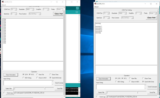
HM-TRLR-D-868 WITH ARDUINO MEGA

HM-TRLR-D-868 COMMUNICATION WITH ARDUINO  MEGA 2560


SENDER SIDE CODE EXAMPLE

//char incomingByte = 0; // for incoming serial data
int cntr = 1;

void setup() {
  Serial.begin(9600);
  Serial1.begin(9600);
  Serial.print("sender\n");
}

void loop() {

  if(Serial.available()> 0)
  {
    //Serial.print("receving::");
    //Serial.println(Serial.read());
    //delay(1000);
    //Serial.print("sending:");
    Serial.println("1234");
    //Serial.write(cntr);
    // Serial.print("\n");
    cntr++;
    //delay(1000);
  }
  else
  {
      Serial.print("0\n");
  }
  delay(1000);


RECEIVER SIDE CODE EXAMPLE

//int counter = 1;

void setup()
{
  Serial.begin(9600);
   Serial1.begin(9600);
  Serial.print("receiver\n");
}

void loop()
{

  if(Serial.available() > 0)
  {
    //int incomingbytes = Serial.read();
    //Serial.print("counter");
   // Serial.write("counter::");
    ///Serial.write(counter);
    //Serial.write(1);
    delay(1000);
    Serial.print("receving::");
   
    //Serial.println(incomingbytes,DEC);
    Serial.print((char)Serial.read());
    Serial.print("\n");
   
    //counter++;
  }
  else
  {
      Serial.print("not available\n");
  }
     
  delay(1000);

}


CONNECTIONS WITH ARDUINO MEGA

ARDUINO MEGA 2560 WITH HM-TRLR-D-868:
Hm-TRLR_868
ARDUINO MEGA 2560
5V
5V
GND
GND
TX
RX
RX
TX
Gnd
Gnd
Sleep
gnd


Tuesday, September 10, 2019

prime number using python

# Python program to check if the input number is prime or not

num = 407

# take input from the user
# num = int(input("Enter a number: "))

# prime numbers are greater than 1
if num > 1:
   # check for factors
   for i in range(2,num):
       if (num % i) == 0:
           print(num,"is not a prime number")
           print(i,"times",num//i,"is",num)
           break
   else:
       print(num,"is a prime number")
     
# if input number is less than
# or equal to 1, it is not prime
else:
   print(num,"is not a prime number")

Arduino Default Fuse bits

Arduino Default Fuse Settings

Here are the default fuse settings for each Arduino from the boards.txt included with the Arduino development software.
To understand more about the fuse settings for your microcontroller, visit Engbedded’s AVR Fuse Calculator.
To write fuse settings, you will need a programmer with this capability. I use Mighty Ohm’s high-voltage rescue shield available here.

Arduino Uno

Low Fuse0xFF
High Fuse0xDE
Extended Fuse0x05

Arduino Duemilanove or Nano w/ ATmega328

Low Fuse0xFF
High Fuse0xDA
Extended Fuse0x05

Arduino Diecimila, Duemilanove, or Nano w/ ATmega168

Low Fuse0xFF
High Fuse0xDD
Extended Fuse0x00

Arduino Mega 2560

Low Fuse0xFF
High Fuse0xD8
Extended Fuse0xFD

Arduino Mega (ATmega1280)

Low Fuse0xFF
High Fuse0xDA
Extended Fuse0xF5

Arduino Mini

Low Fuse0xFF
High Fuse0xDD
Extended Fuse0x00

Arduino Fio

Low Fuse0xFF
High Fuse0xDA
Extended Fuse0x05

Arduino BT w/ ATmega328

Low Fuse0xFF
High Fuse0xD8
Extended Fuse0x05

Arduino BT w/ ATmega168

Low Fuse0xFF
High Fuse0xDD
Extended Fuse0x00

LilyPad Arduino w/ ATmega328

Low Fuse0xFF
High Fuse0xDA
Extended Fuse0x05

LilyPad Arduino w/ ATmega168

Low Fuse0xE2
High Fuse0xDD
Extended Fuse0x00

Arduino Pro or Pro Mini (5V, 16 MHz) w/ ATmega328

Low Fuse0xFF
High Fuse0xDA
Extended Fuse0x05

Arduino Pro or Pro Mini (5V, 16 MHz) w/ ATmega168

Low Fuse0xFF
High Fuse0xDD
Extended Fuse0x00

Arduino Pro or Pro Mini (3.3V, 8 MHz) w/ ATmega328

Low Fuse0xFF
High Fuse0xDA
Extended Fuse0x05

Arduino Pro or Pro Mini (3.3V, 8 MHz) w/ ATmega168

Low Fuse0xC6
High Fuse0xDD
Extended Fuse0x00

Arduino NG or older w/ ATmega168

Low Fuse0xFF
High Fuse0xDD
Extended Fuse0x00

Arduino NG or older w/ ATmega8

Low Fuse0xDF
High Fuse0xCA

python class topic video