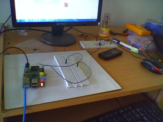
Now a days Arduino is very famous development Board , Using different places in electronics and projects and making of the different products.
About ZigBee:
About ZigBee:
ZigBee is a specification for a
suite of high level communication protocols used to create personal area networks built from
small, low-power digital radios. ZigBee is based on an IEEE 802.15
standard. Though low-powered, ZigBee devices can transmit data over
long distances by passing data through intermediate devices to reach more
distant ones, creating a mesh network;
i.e., a network with no centralized control or high-power transmitter/receiver
able to reach all of the networked devices. The decentralized nature of
such wireless ad hoc networks make them
suitable for applications where a central node can't be relied upon.
ZigBee is used in
applications that require only a low data rate, long battery life, and secure
networking. ZigBee has a defined rate of 250 kbit/s, best suited for periodic
or intermittent data or a single signal transmission from a sensor or input
device. Applications include wireless light switches, electrical meters with
in-home-displays, traffic management systems, and other consumer and industrial
equipment that requires short-range wireless transfer of data at relatively low
rates. The technology defined by the ZigBee specification is intended to be
simpler and less expensive than other WPANs, such as Bluetooth or Wi-Fi.
ZigBee networks are
secured by 128 bit symmetric encryption keys. In home
automation applications, transmission distances range from 10 to 100
meters line-of-sight, depending on power output
and environmental characteristics.
ZigBee was conceived
in 1998, standardized in 2003, and revised in 2006. The name refers to
the waggle dance of honey bees after their
return to the beehive.
Device types and operating modes
ZigBee devices are of three types:
- ZigBee Coordinator (ZC): The most capable device, the Coordinator forms the root of the network tree and might bridge to other networks. There is exactly one ZigBee Coordinator in each network since it is the device that started the network originally (the ZigBee LightLink specification also allows operation without a ZigBee Coordinator, making it more usable for over-the-shelf home products). It stores information about the network, including acting as the Trust Center & repository for security keys.[24][25]
- ZigBee Router (ZR): As well as running an application function, a Router can act as an intermediate router, passing on data from other devices.
- ZigBee End Device (ZED): Contains just enough functionality to talk to the parent node (either the Coordinator or a Router); it cannot relay data from other devices. This relationship allows the node to be asleep a significant amount of the time thereby giving long battery life. A ZED requires the least amount of memory, and therefore can be less expensive to manufacture than a ZR or ZC.
The current ZigBee protocols support beacon and non-beacon enabled networks. In non-beacon-enabled networks, an unslotted CSMA/CA channel access mechanism is used. In this type of network, ZigBee Routers typically have their receivers continuously active, requiring a more robust power supply. However, this allows for heterogeneous networks in which some devices receive continuously, while others only transmit when an external stimulus is detected. The typical example of a heterogeneous network is a wireless light switch: The ZigBee node at the lamp may receive constantly, since it is connected to the mains supply, while a battery-powered light switch would remain asleep until the switch is thrown. The switch then wakes up, sends a command to the lamp, receives an acknowledgment, and returns to sleep. In such a network the lamp node will be at least a ZigBee Router, if not the ZigBee Coordinator; the switch node is typically a ZigBee End Device.
In beacon-enabled networks, the special network nodes called ZigBee Routers transmit periodic beacons to confirm their presence to other network nodes. Nodes may sleep between beacons, thus lowering their duty cycle and extending their battery life. Beacon intervals depend on data rate; they may range from 15.36 milliseconds to 251.65824 seconds at 250 kbit/s, from 24 milliseconds to 393.216 seconds at 40 kbit/s and from 48 milliseconds to 786.432 seconds at 20 kbit/s. However, low duty cycle operation with long beacon intervals requires precise timing, which can conflict with the need for low product cost.
In general, the ZigBee protocols minimize the time the radio is on, so as to reduce power use. In beaconing networks, nodes only need to be active while a beacon is being transmitted. In non-beacon-enabled networks, power consumption is decidedly asymmetrical: some devices are always active, while others spend most of their time sleeping.
Except for the Smart Energy Profile 2.0, ZigBee devices are required to conform to the IEEE 802.15.4-2003 Low-Rate Wireless Personal Area Network (LR-WPAN) standard. The standard specifies the lower protocol layers—the physical layer (PHY), and the media access control portion of the data link layer (DLL). The basic channel access mode is "carrier sense, multiple access/collision avoidance" (CSMA/CA). That is, the nodes talk in the same way that humans converse; they briefly check to see that no one is talking before they start, with three notable exceptions. Beacons are sent on a fixed timing schedule and do not use CSMA. Message acknowledgments also do not use CSMA. Finally, devices in beacon-enabled networks that have low latency real-time requirements may also use Guaranteed Time Slots (GTS), which by definition do not use CSMA.
for the more information please visit the below links
http://potentiallabs.com/cart/automatic-station-name-display-in-train-using-zigbee?search=zigbee
detailed video please visit the youtube link ....
https://www.youtube.com/watch?v=SBjvDa1uC3E
for the more information please visit the below links
http://potentiallabs.com/cart/automatic-station-name-display-in-train-using-zigbee?search=zigbee
detailed video please visit the youtube link ....
https://www.youtube.com/watch?v=SBjvDa1uC3E


